

Product Description:
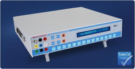
A benchtop digital multimeter that combines high performance and accuracy with simple operation.With speed and precision, the 5075 easily measures from nanovolts to 10kV, from picoamps to 30 Amps, from nano-ohms up to 1GΩ, and from picofarads to 300μF. It is ideal for users requiring a cost-effective DMM with multiple functions and exceptional resolution and accuracy up to 7½ digits. This makes the 5075 is a versatile solution to essential laboratory calibration and verification, covering a wide range of applications with excellent measurement capabilities, whilst maintaining reliability and performance.
The Auto Dynamic Filter (ADF) mode allows the 5075 to automatically select the most suitable filter. For a fast changing signal or for when the signal is first connected the reading is displayed almost immediately, but if the input remains constant, the filter time is increased to provide a more stable accurate reading. If the input were disconnected the filter would immediately return to the fastest.
Operation is simple, all major functions from range selection to null require just one key press. The large 24 digit display shows clearly the range and reading and can even show the time to the next sample if required. Other functions can be easily selected from a scrolled menu.
Functions for diode/zener tests, max/min, peak hold and continuity checks are available and also various audible warnings can be selected.
A bar graph function allows the user to program high and low pass/fail limits and switch to the bar display mode. This will give an audible and visual indication to the user of the components specification.
A low thermal, 10-channel scanner option, allows multiple inputs to be displayed or compared without the additional cost and inconvenience of a separate switching arrangement.
EasyCal Software – Manage, Automate and Optimise the Calibration Process
Connect the 5075 to a PC/Laptop via GPIB (USB optional) installed with Time Electronics’ EasyCal software and automate the calibration process. This provides increased speed of calibration and consistency of results. Easily produce calibration certificates and reports to ISO 9001, ISO 17025, and other international quality standards.
Technical Specification:
Accuracy specified as ± ppm reading + ± Floor at default resolution (shown in brackets), relative to calibration standards. TCAL = 20°C
| DC VOLTAGE | |||
|---|---|---|---|
| RANGE | RESOLUTION (AT DEFAULT IN BRACKETS) | 90 DAY ± 5°C | 1 YEAR ± 5°C |
| 0 to 3mV / 0 to 10mV | 10nV (10nV) | 22 + 80nV | 30 + 80nV |
| 0 to 30mV / 0 to 100mV | 10nV (100nV) | 22 + 800nV | 30 + 800nV |
| 0 to 300mV 0 to 1V |
100nV (1μV) | 22 + 8μV 12 + 6μV |
30 + 8μV 18 + 6μV |
| 0 to 3V / 0 to 10V | 1μV (10μV) | 12 + 60μV | 18 + 60μV |
| 0 to 30V / 0 to 100V | 10μV (100μV) | 20 + 600μV | 30 + 600μV |
| 0 to 300V / 0 to 1kV | 100μV (1mV) | 22 + 8mV | 30 + 8mV |
| 0 to 3kV / 0 to 10kV | 1mV (10mV) | 250 + 1V | 350 + 1.2V |
All DCV specifications ± 0.4μV
| DC CURRENT | |||
|---|---|---|---|
| RANGE | RESOLUTION (AT DEFAULT IN BRACKETS) | 90 DAY ± 5°C | 1 YEAR ± 5°C |
| 0 to 3μA / 0 to10μA | 10pA (10pA) | 150 + 200pA | 200 + 250pA |
| 0 to 30μA / 0 to 100μA | 100pA (100pA) | 75 + 1nA | 100 + 1nA |
| 0 to 300μA / 0 to 1mA | 100pA (1nA) | 75 + 10nA | 100 + 10nA |
| 0 to 3mA / 0 to 10mA | 1nA (10nA) | 75 + 100nA | 100 + 100nA |
| 0 to 30mA / 0 to 100mA | 10nA (100nA) | 75 + 1μA | 100 + 1μA |
| 0 to 300mA / 0 to 1A | 100nA (1μA) | 150 + 10μA | 200 + 10μA |
| 0 to 3A / 0 to 10A | 10μA (10μA) | 500 + 200μA | 750 + 200μA |
| 0 to 30A | 100μA (100μA) | 500 + 2mA | 750 + 2mA |
| AC VOLTAGE | |||
|---|---|---|---|
| RANGE | RESOLUTION* | 90 DAY ± 5°C | 1 YEAR ± 5°C |
| 0 to 30mV | 1μV | 0.05% + 4μV | 0.06% + 4μV |
| 0 to 300mV | 10μV | 0.05% + 40μV | 0.06% + 40μV |
| 0 to 3V | 100μV | 0.05% + 400μV | 0.06% + 400μV |
| 0 to 30V | 1mV | 0.05% + 4mV | 0.06% + 4mV |
| 0 to 300V | 10mV | 0.15% + 0.1V | 0.2% + 0.12V |
| 0 to 3kV | 100mV | 0.15% + 1V | 0.2% + 1.2V |
* Voltage AC + DC / Current AC + DC
Total measurement error will not exceed the sum of the separate AC + DC accuracy specification, plus one display digit.
All AC Voltages ± 50μV
| AC CURRENT | |||
|---|---|---|---|
| RANGE | RESOLUTION* | 90 DAY ± 5°C | 1 YEAR ± 5°C |
| 0 to 30μA | 1nA | 0.1% + 8nA | 0.2% + 10nA |
| 0 to 300μA | 10nA | 0.1% + 80nA | 0.2% + 100nA |
| 0 to 3mA | 100nA | 0.1% + 800nA | 0.2% + 1μA |
| 0 to 30mA | 1μA | 0.1% + 8μA | 0.2% + 10μA |
| 0 to 300mA | 10μA | 0.1% + 80μA | 0.2% + 100μA |
| 0 to 3A | 100μA | 0.15% + 1mA | 0.2% + 1mA |
| 0 to 30A | 1mA | 0.15% + 10mA | 0.2% + 10mA |
* Voltage AC + DC / Current AC + DC
Total measurement error will not exceed the sum of the separate AC + DC accuracy specification, plus one display digit.
All AC Current ± 50nA
| RESISTANCE | |||
|---|---|---|---|
| RANGE | RESOLUTION (AT DEFAULT IN BRACKETS) | 90 DAY ± 5°C | 1 YEAR ± 5°C |
| 0 to 30mΩ / 0 to 100mΩ | 10nΩ (100nΩ) | 70 + 2μΩ | 100 + 2.5μΩ |
| 0 to 300mΩ / 0 to 1Ω | 100nΩ (1μΩ) | 40 + 10μΩ | 60 + 15μΩ |
| 0 to 3Ω / 0 to 10Ω | 1μΩ (10μΩ) | 30 + 80μΩ | 40 + 100μΩ |
| 0 to 30Ω / 0 to100Ω | 10μΩ (100μΩ) | 20 + 600μΩ | 30 + 800μΩ |
| 0 to 300Ω / 0 to 1kΩ | 100uΩ (1mΩ) | 20 + 6mΩ | 30 + 8mΩ |
| 0 to 3kΩ / 0 to 10kΩ | 1mΩ (10mΩ) | 20 + 60mΩ | 30 + 80mΩ |
| 0 to 30kΩ / 0 to 100kΩ | 10mΩ (100mΩ) | 30 + 600mΩ | 45 + 800mΩ |
| 0 to 300kΩ / 0 to 1MΩ | 100mΩ (1Ω) | 60 + 8Ω | 90 + 10Ω |
| 0 to 3MΩ / 0 to 10MΩ | 1Ω (10Ω) | 100 + 100Ω | 150 + 120Ω |
| 0 to 30MΩ / 0 to 100MΩ | 100Ω (100Ω) | 750 + 10kΩ | 1000 + 10kΩ |
| 0 to 300MΩ / 0 to 1GΩ | 10kΩ (10kΩ) | 0.5% + 1MΩ | 0.75% + 1MΩ |
2 wire ranges begin at 300mΩ. Accuracy applies to 2 and 4 wire resistances
| PRT (PT100) TEMPERATURE | |||
|---|---|---|---|
| RANGE | RESOLUTION | 90 DAY ± 5°C | 1 YEAR ± 5°C |
| -200 to +600°C | 0.001°C | 0.05°C | 0.06°C |
NOTE: Only available in four terminal mode on the 300Ω range.
| FREQUENCY | |||
|---|---|---|---|
| RANGE | RESOLUTION | 90 DAY ± 5°C | 1 YEAR ± 5°C |
| 0 to 100kHz | 1Hz | 10 + 1 | 12 + 1 |
NOTE: Frequency may be measured on either voltage or current inputs if the AC option has been fitted.
| CAPACITANCE | |||
|---|---|---|---|
| RANGE | RESOLUTION (5 DIGIT) | 90 DAY ± 5°C | 1 YEAR ± 5°C |
| 0 to 30nF | 1pF | 0.2% + 20pF | 0.25% + 20pF |
| 0 to 300nF | 10pF | 0.2% + 200pF | 0.25% + 200pF |
| 0 to 3μF | 100pF | 0.2% + 2nF | 0.25% + 2nF |
| 0 to 30μF | 1nF | 0.2% + 20nF | 0.25% + 20nF |
| 0 to 300μF | 10nF | 0.2% + 200nF | 0.25% + 200nF |
All Capacitances ± 1pF
Accuracy stated as 90 day and 1 year specification for all ranges ± 5°C in 6 digit mode for DC and 6 digit mode for AC
| BASIC FUNCTIONS | |
|---|---|
| N Digits | Changes the reading resolution, which can be changed from 4 up to 7 digits, (depending on the scale selected). |
| Null | Null facility is available on all DC ranges, Ohms and Capacitance. Null is not available on AC or frequency. When this key is pressed, the DMM will accept the measured present value as the zero value for the range selected. If auto-range is on, the unit will null each range. This is useful for cancelling an offset voltage or for zeroing the value of the test leads on resistance. |
| Auto Ranging | Auto-range (AUTO) will select the optimum range for the measurement. This will introduce very little delay for the operator. The indicator above the keypad will show when the DMM is in auto-range mode. |
| Filter | The filter alters the integration time of the reading. Filter times are 150ms, 250ms, 500ms, 1s, 2s, 4s, 8s, 16s, 32s & off. |
| Internal Temperature | Internal Temperature controlled at 35˚C ± 2˚C with an ambient temperature of 20 to 28˚C |
| ADVANCED FUNCTIONS | |
|---|---|
| Ohms Compensation | Cancels the effects of any offset voltages by first measuring the input voltage with the current source on and the measuring the voltage with the current source off. The induced voltage is the difference between the two voltages, thus giving a more accurate reading. Can be used in 2 and 4 wire mode for measurements up to 100kΩ. Ohms compensation doesn’t work on ranges above 100kΩ. |
| Diode / Zener Diode Test | The diode test function will passes a current of 1mA through the diode under test and displays the diode forward voltage. May be used for zener diodes up to 10V. |
| Self Test Reset | The instrument can perform a self-test of all its digital circuits including the IEEE and RAM. |
| Max – Min | This function displays the maximum and minimum readings of the input. By using the up and down keys the Maximum, Minimum or Present value input may be displayed. |
| Peak Hold | This function will display the peak value measured. By using the up and down keys the Peak value or Present input may be displayed. |
| Component Test | Used for component selection. If a component to be tested must fall between a high and low value, component test can be used to make the selection process quicker. It provides a visual display which moves a pointer between the high and low values input, and also indicates whether the component is higher or lower in value than the high and low points if it doesn’t fall between them. |
| PRT Temp | PT100 elements can be measured and displayed in ˚C using this function. |
| Dual Display | Display Voltage and frequency of the input or the current and frequency (if the AC module has been installed), for AC inputs. |
| Analogue Filter | The analogue filter can be switched into the input circuit to remove any high frequency noise that may be present on the input. |
| Auto Dynamic Filter: | The Auto dynamic filter automatically selects the most appropriate filter period. The auto dynamic filter will increase or decrease the filter period (up to the maximum set using the filter key) depending upon the stability of the input signal. |
| Continuity / Sample Beep | Continuity tests can be performed by selecting this option when in resistance mode. Any value below 30% of the full range will produce the continuity beep. Sample beep alerts the operator to a new reading being displayed. |
| Internal Date / Time | Date and Time can be displayed or entered using this option. |
| Internal Temp | The internal temperature of the 5075 can be displayed and is updated approximately every 5 minutes. The internal temperature is used to perform an internal calibration when the temperature varies by 1˚C, thus insuring the temperature coefficient of the unit remains negligible. |
| Remote Control | This instrument implements the requirements of the IEEE – 488/1978 standard. The IEEE – 488 interface, allows remote control of the instrument by a suitable computer or controller. Repetitive calibration work can be speedily and accurately carried out, giving printed results if required. The main limitations of the IEEE are :-
1) A maximum of 15 devices on the bus. 2) The maximum bus length should not be greater than 20m or number of devices x 2, which ever is the shorter. |
| Scanner Option | The scanner option for the 5075 DMM consists of an internally fitted relay board. This board provides 10 input channels. Up to two boards may be fitted giving up to 20 channels. The relays switch all 4 input terminals: V+, V-, I+, I– to one of 10/20 inputs via the 25 way ‘D’ connectors. The scanner card may be used for voltage, current, resistance, capacitance, frequency, and PT100.
Scanner Specifications |
| Operating Temperature | 0 to 50˚C |
| Line Power | 110/220/240V AC, 50/60Hz |
| Standard Interfaces | GPIB (USB adaptor optional) |
| Dimensions | W423 x H89 x D415mm |
| Weight | 8.5kg |
| Country of Origin | UK |
- Açıklama
Product Description:
A benchtop digital multimeter that combines high performance and accuracy with simple operation.With speed and precision, the 5075 easily measures from nanovolts to 10kV, from picoamps to 30 Amps, from nano-ohms up to 1GΩ, and from picofarads to 300μF. It is ideal for users requiring a cost-effective DMM with multiple functions and exceptional resolution and accuracy up to 7½ digits. This makes the 5075 is a versatile solution to essential laboratory calibration and verification, covering a wide range of applications with excellent measurement capabilities, whilst maintaining reliability and performance.
The Auto Dynamic Filter (ADF) mode allows the 5075 to automatically select the most suitable filter. For a fast changing signal or for when the signal is first connected the reading is displayed almost immediately, but if the input remains constant, the filter time is increased to provide a more stable accurate reading. If the input were disconnected the filter would immediately return to the fastest.
Operation is simple, all major functions from range selection to null require just one key press. The large 24 digit display shows clearly the range and reading and can even show the time to the next sample if required. Other functions can be easily selected from a scrolled menu.
Functions for diode/zener tests, max/min, peak hold and continuity checks are available and also various audible warnings can be selected.
A bar graph function allows the user to program high and low pass/fail limits and switch to the bar display mode. This will give an audible and visual indication to the user of the components specification.
A low thermal, 10-channel scanner option, allows multiple inputs to be displayed or compared without the additional cost and inconvenience of a separate switching arrangement.
EasyCal Software – Manage, Automate and Optimise the Calibration Process
Connect the 5075 to a PC/Laptop via GPIB (USB optional) installed with Time Electronics’ EasyCal software and automate the calibration process. This provides increased speed of calibration and consistency of results. Easily produce calibration certificates and reports to ISO 9001, ISO 17025, and other international quality standards.Technical Specification:
Accuracy specified as ± ppm reading + ± Floor at default resolution (shown in brackets), relative to calibration standards. TCAL = 20°C
DC VOLTAGE RANGE RESOLUTION (AT DEFAULT IN BRACKETS) 90 DAY ± 5°C 1 YEAR ± 5°C 0 to 3mV / 0 to 10mV 10nV (10nV) 22 + 80nV 30 + 80nV 0 to 30mV / 0 to 100mV 10nV (100nV) 22 + 800nV 30 + 800nV 0 to 300mV
0 to 1V100nV (1μV) 22 + 8μV
12 + 6μV30 + 8μV
18 + 6μV0 to 3V / 0 to 10V 1μV (10μV) 12 + 60μV 18 + 60μV 0 to 30V / 0 to 100V 10μV (100μV) 20 + 600μV 30 + 600μV 0 to 300V / 0 to 1kV 100μV (1mV) 22 + 8mV 30 + 8mV 0 to 3kV / 0 to 10kV 1mV (10mV) 250 + 1V 350 + 1.2V All DCV specifications ± 0.4μV
DC CURRENT RANGE RESOLUTION (AT DEFAULT IN BRACKETS) 90 DAY ± 5°C 1 YEAR ± 5°C 0 to 3μA / 0 to10μA 10pA (10pA) 150 + 200pA 200 + 250pA 0 to 30μA / 0 to 100μA 100pA (100pA) 75 + 1nA 100 + 1nA 0 to 300μA / 0 to 1mA 100pA (1nA) 75 + 10nA 100 + 10nA 0 to 3mA / 0 to 10mA 1nA (10nA) 75 + 100nA 100 + 100nA 0 to 30mA / 0 to 100mA 10nA (100nA) 75 + 1μA 100 + 1μA 0 to 300mA / 0 to 1A 100nA (1μA) 150 + 10μA 200 + 10μA 0 to 3A / 0 to 10A 10μA (10μA) 500 + 200μA 750 + 200μA 0 to 30A 100μA (100μA) 500 + 2mA 750 + 2mA AC VOLTAGE RANGE RESOLUTION* 90 DAY ± 5°C 1 YEAR ± 5°C 0 to 30mV 1μV 0.05% + 4μV 0.06% + 4μV 0 to 300mV 10μV 0.05% + 40μV 0.06% + 40μV 0 to 3V 100μV 0.05% + 400μV 0.06% + 400μV 0 to 30V 1mV 0.05% + 4mV 0.06% + 4mV 0 to 300V 10mV 0.15% + 0.1V 0.2% + 0.12V 0 to 3kV 100mV 0.15% + 1V 0.2% + 1.2V * Voltage AC + DC / Current AC + DC
Total measurement error will not exceed the sum of the separate AC + DC accuracy specification, plus one display digit.All AC Voltages ± 50μV
AC CURRENT RANGE RESOLUTION* 90 DAY ± 5°C 1 YEAR ± 5°C 0 to 30μA 1nA 0.1% + 8nA 0.2% + 10nA 0 to 300μA 10nA 0.1% + 80nA 0.2% + 100nA 0 to 3mA 100nA 0.1% + 800nA 0.2% + 1μA 0 to 30mA 1μA 0.1% + 8μA 0.2% + 10μA 0 to 300mA 10μA 0.1% + 80μA 0.2% + 100μA 0 to 3A 100μA 0.15% + 1mA 0.2% + 1mA 0 to 30A 1mA 0.15% + 10mA 0.2% + 10mA * Voltage AC + DC / Current AC + DC
Total measurement error will not exceed the sum of the separate AC + DC accuracy specification, plus one display digit.All AC Current ± 50nA
RESISTANCE RANGE RESOLUTION (AT DEFAULT IN BRACKETS) 90 DAY ± 5°C 1 YEAR ± 5°C 0 to 30mΩ / 0 to 100mΩ 10nΩ (100nΩ) 70 + 2μΩ 100 + 2.5μΩ 0 to 300mΩ / 0 to 1Ω 100nΩ (1μΩ) 40 + 10μΩ 60 + 15μΩ 0 to 3Ω / 0 to 10Ω 1μΩ (10μΩ) 30 + 80μΩ 40 + 100μΩ 0 to 30Ω / 0 to100Ω 10μΩ (100μΩ) 20 + 600μΩ 30 + 800μΩ 0 to 300Ω / 0 to 1kΩ 100uΩ (1mΩ) 20 + 6mΩ 30 + 8mΩ 0 to 3kΩ / 0 to 10kΩ 1mΩ (10mΩ) 20 + 60mΩ 30 + 80mΩ 0 to 30kΩ / 0 to 100kΩ 10mΩ (100mΩ) 30 + 600mΩ 45 + 800mΩ 0 to 300kΩ / 0 to 1MΩ 100mΩ (1Ω) 60 + 8Ω 90 + 10Ω 0 to 3MΩ / 0 to 10MΩ 1Ω (10Ω) 100 + 100Ω 150 + 120Ω 0 to 30MΩ / 0 to 100MΩ 100Ω (100Ω) 750 + 10kΩ 1000 + 10kΩ 0 to 300MΩ / 0 to 1GΩ 10kΩ (10kΩ) 0.5% + 1MΩ 0.75% + 1MΩ 2 wire ranges begin at 300mΩ. Accuracy applies to 2 and 4 wire resistances
PRT (PT100) TEMPERATURE RANGE RESOLUTION 90 DAY ± 5°C 1 YEAR ± 5°C -200 to +600°C 0.001°C 0.05°C 0.06°C NOTE: Only available in four terminal mode on the 300Ω range.
FREQUENCY RANGE RESOLUTION 90 DAY ± 5°C 1 YEAR ± 5°C 0 to 100kHz 1Hz 10 + 1 12 + 1 NOTE: Frequency may be measured on either voltage or current inputs if the AC option has been fitted.
CAPACITANCE RANGE RESOLUTION (5 DIGIT) 90 DAY ± 5°C 1 YEAR ± 5°C 0 to 30nF 1pF 0.2% + 20pF 0.25% + 20pF 0 to 300nF 10pF 0.2% + 200pF 0.25% + 200pF 0 to 3μF 100pF 0.2% + 2nF 0.25% + 2nF 0 to 30μF 1nF 0.2% + 20nF 0.25% + 20nF 0 to 300μF 10nF 0.2% + 200nF 0.25% + 200nF All Capacitances ± 1pF
Accuracy stated as 90 day and 1 year specification for all ranges ± 5°C in 6 digit mode for DC and 6 digit mode for AC
BASIC FUNCTIONS N Digits Changes the reading resolution, which can be changed from 4 up to 7 digits, (depending on the scale selected). Null Null facility is available on all DC ranges, Ohms and Capacitance. Null is not available on AC or frequency. When this key is pressed, the DMM will accept the measured present value as the zero value for the range selected. If auto-range is on, the unit will null each range. This is useful for cancelling an offset voltage or for zeroing the value of the test leads on resistance. Auto Ranging Auto-range (AUTO) will select the optimum range for the measurement. This will introduce very little delay for the operator. The indicator above the keypad will show when the DMM is in auto-range mode. Filter The filter alters the integration time of the reading. Filter times are 150ms, 250ms, 500ms, 1s, 2s, 4s, 8s, 16s, 32s & off. Internal Temperature Internal Temperature controlled at 35˚C ± 2˚C with an ambient temperature of 20 to 28˚C ADVANCED FUNCTIONS Ohms Compensation Cancels the effects of any offset voltages by first measuring the input voltage with the current source on and the measuring the voltage with the current source off. The induced voltage is the difference between the two voltages, thus giving a more accurate reading. Can be used in 2 and 4 wire mode for measurements up to 100kΩ. Ohms compensation doesn’t work on ranges above 100kΩ. Diode / Zener Diode Test The diode test function will passes a current of 1mA through the diode under test and displays the diode forward voltage. May be used for zener diodes up to 10V. Self Test Reset The instrument can perform a self-test of all its digital circuits including the IEEE and RAM. Max – Min This function displays the maximum and minimum readings of the input. By using the up and down keys the Maximum, Minimum or Present value input may be displayed. Peak Hold This function will display the peak value measured. By using the up and down keys the Peak value or Present input may be displayed. Component Test Used for component selection. If a component to be tested must fall between a high and low value, component test can be used to make the selection process quicker. It provides a visual display which moves a pointer between the high and low values input, and also indicates whether the component is higher or lower in value than the high and low points if it doesn’t fall between them. PRT Temp PT100 elements can be measured and displayed in ˚C using this function. Dual Display Display Voltage and frequency of the input or the current and frequency (if the AC module has been installed), for AC inputs. Analogue Filter The analogue filter can be switched into the input circuit to remove any high frequency noise that may be present on the input. Auto Dynamic Filter: The Auto dynamic filter automatically selects the most appropriate filter period. The auto dynamic filter will increase or decrease the filter period (up to the maximum set using the filter key) depending upon the stability of the input signal. Continuity / Sample Beep Continuity tests can be performed by selecting this option when in resistance mode. Any value below 30% of the full range will produce the continuity beep. Sample beep alerts the operator to a new reading being displayed. Internal Date / Time Date and Time can be displayed or entered using this option. Internal Temp The internal temperature of the 5075 can be displayed and is updated approximately every 5 minutes. The internal temperature is used to perform an internal calibration when the temperature varies by 1˚C, thus insuring the temperature coefficient of the unit remains negligible. Remote Control This instrument implements the requirements of the IEEE – 488/1978 standard. The IEEE – 488 interface, allows remote control of the instrument by a suitable computer or controller. Repetitive calibration work can be speedily and accurately carried out, giving printed results if required. The main limitations of the IEEE are :- 1) A maximum of 15 devices on the bus.
2) The maximum bus length should not be greater than 20m or number of devices x 2, which ever is the shorter.
Scanner Option The scanner option for the 5075 DMM consists of an internally fitted relay board. This board provides 10 input channels. Up to two boards may be fitted giving up to 20 channels. The relays switch all 4 input terminals: V+, V-, I+, I– to one of 10/20 inputs via the 25 way ‘D’ connectors. The scanner card may be used for voltage, current, resistance, capacitance, frequency, and PT100. Scanner Specifications
Maximum voltage: 200V DC / 150V AC Maximum current: 1A DC / 1A AC
Thermal EMF: Less than 2μV per contact Contact resistance: Less than 150mΩ
Operating life: Up to 200 million operations Operating time: 20msOperating Temperature 0 to 50˚C Line Power 110/220/240V AC, 50/60Hz Standard Interfaces GPIB (USB adaptor optional) Dimensions W423 x H89 x D415mm Weight 8.5kg Country of Origin UK


